Why do I care about Plant Sizing?
As part of doing early stage analysis of building design, you may want to consider how different design options affect the overall central plant sizing.
For many systems envelope improvements can have a much bigger impact on air-handling unit and chiller size than on energy as a percentage of the total capacity. These improvements may lead to reductions in space requirements, equipment costs and other benefits which in turn justify the envelope strategies used.
Similarly if you're comparing HVAC options, you will want to be able to communicate to decision-makers how different HVAC system options affect the amount of plant and equipment required. A good example is the comparison between all-air systems, such as VAV systems and DOAS systems. Often the central air distribution between these systems will be substantially different.
The Plant Sizing Tab is designed to help you make these apples-to-apples comparisons, even if systems are quite different in design.
Plant Sizing - Heating - what is it?
The top-right component in the Plant Sizing tab is the Heating section. The aim of this is to provide you with a rolled-up comparable summary of what the total heating equipment requirements are on a project (whatever they may be) and what they're made up of.
If you click "Expand outputs" you'll see 5 outputs and each is explained below.
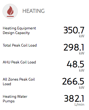 (SI)
(SI) 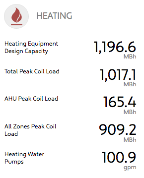 (IP)
(IP)
All Zones Peak Coil Load
This is the total sizing for the heating coils that are attached to any heating equipment inside of all the zones in a building.
Almost all systems incorporate zone heating systems and this covers all applications including:
- VAV box heating coils
- Heating coils in fan coil units
- Refrigerant coils in fan coil units providing heating, such as in a Package Terminal Heat Pump
- Electric coils
- Radiant Floor Heating
All of the above are considered to be "coils" for the purposes of this calculation.
Coincidental loads vs Sum of Peaks
We use the HVAC system you've selected to determine whether we publish the peak coincidental load for all the zones or the sum of peaks.
Generally speaking, systems which use a central heating hot water loop system, like a boiler, to provide heating are assumed to be designed to serve a coincidental load where as systems which are individual units (like PTHPs (Split Systems)) are assumed to be cumulative and we publish sum of peaks for this number.
Generally speaking unless there are unusual heating loads in the core zones, the coincidental loads and the sum of peaks will be the same.
Notes about EnergyPlus and what values we use
To size each zone, we look at the load that EnergyPlus tells us has been added to the space for every hour in each sizing day. Note we take this value rather than the equipment size value because after having done comparative studies and tests, we feel this is a much more reliable output for equipment size. This means that if you take equipment sizes directly from EnergyPlus runs, the outputs may not match. You need to take the output that is the load removed from the space in that particular hour.
AHU Peak Coil Load
This is the peak load seen by the heating coil in the Air Handling Unit for the HVAC system. This air at the pre-AHU heating Coil design condition being heated up to whatever the supply air condition is.
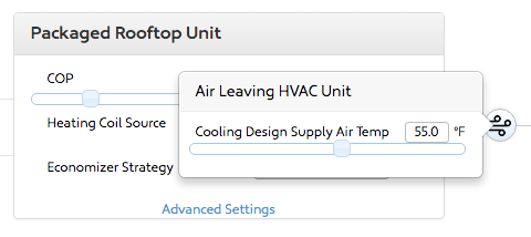
For all systems you can adjust the design supply air dry bulb condition from the AHU using the air-icon after the AHU. For DOAS systems you can also adjust the design supply air dew-point.
All systems have an AHU of some description (even if you can set it up to behave more like a heat recovery ventilator) and for most systems cooling is on as a default.
For many systems, this load will be negligible or zero. DOAS systems default to a supply air temperature of 13C with 50% sensible heat recovery - in many cases this means that the heating coil capacity will be zero.
Total Peak Coil Load
For systems with central heating hot water water plant, this is the coincidental peak between the coil loads occurring in the zones and the coil load seen at the AHU.
For systems with separate plant for the AHU (eg direct gas at the AHU for a DOAS system) this is the sum of the AHU Peak Coil Load and the All-Zones Peak Coil Load.
Heating Equipment Design Capacity
This generic term is meant to describe the total capacity of heating equipment that is needed for the building.
Some customers ask why it's not called Boiler Capacity. It is not called Boiler Design Capacity because if someone decided to swap a heating hot water coil for an electric element then technically the electric capacity should be excluded from this value. Both systems have heating equipment which is why we use this term. We felt there was more value in being able to compare total heating requirements for this output.
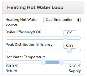
For systems with heating hot water water, it will be higher than the Total Peak Coil Load if the Peak Distribution Efficiency in the Water-side Input Tab is less than 1 (the default is 0.85 - see below). This value is meant to represent losses at the design condition from heat loss in the heating hot water distribution.
For systems that have point of use heating, no losses are assumed and this value will be equal to the Total Peak Coil Load.
Heating Hot Water Pumps
If your system has a heating hot water loop then we will calculate the total pumping capacity required.
This is a function of the Heating Equipment Design Capacity and the delta-T entered in the Heating Water Loop Supply and Return temperatures.
Comments